martes, 9 de septiembre de 2014

IMPERATIVE - Differential Carrier Installation

Differential Installation Instructions
Please read completely before beginning.
Disassembly


Make sure that you have all the parts and tools you will need. The extent of disassembly depends on the job being done and the inspection findings. Lift the vehicle using an appropriate lift or a jack and safe jack stands. Always make certain that the vehicle is safely supported before working underneath. 
Unbolt the driveshaft from the yoke. 
Remove the differential cover or unbolt the third member. Let the oil drain into a suitable container. 
Please recycle your waste oil. 
Remove c-clip axles by removing the differential cross pin bolt and cross pin shaft, pushing the axles in and pulling the c-clips. Full float axles are unbolted at the hubs. 

Punch both carrier caps with identification marks so that you will be able to re-install them on the same side and in the same direction. Most carriers can be pried out of the housing with a pry bar. Further disassembly depends on the job being done. If you’re changing the ring and pinion or the pinion bearings, remove the pinion nut with an air gun while holding the yoke, or use a long breaker bar and brace the yoke (bolt it to a long board) so that it can’t move. 
Knock the pinion gear out to the rear with a brass punch, taking care not to damage the threads. 
Keep track of the location and thickness of all of the original shims. Pinion bearings must be pressed off. Carrier bearings can be pulled using a bearing puller. Internal parts (inside the carrier) can be removed as necessary.

                                      Source: http://www.differentials.com/technical-help/installation-instructions


lunes, 1 de septiembre de 2014

PRACTICA: TRADUCCION: ROTATION, TORQUES


Rotational kinetic energy

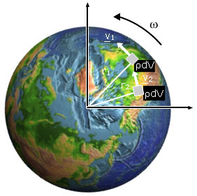
Let us picture a rigid body turning with angular velocity ω, like the Earth in this picture. Mentally,
let's divide it up into a collection of small masses. With respect to the axis of rotation, a single mass m at radius r is travelling at speed of 

                v = rω
 (You may revise circular motion at this point.) Its kinetic energy is ½ mv2. So let's imagine the dividing the object up into many masses mi at distances rifrom the axis. Each has vi = riω, where ω has the same value for all the masses because the object is (by assumption) rigid. So the total rotational kinetic energy is

Krot= Σ Ki= Σ ½ miri2ω2

where the summation is over all of the i. ½ ω2 is a common factor in every term of the sum, so

Krot= ½(Σ miri2)ω2 = ½ Iω2 where

I = Σ miri2is the moment of inertia 


This is the result for a collection of discrete masses, mi. For a continuous body, we should normally divide it up into small elements of volume, dV. (You can revise calculus.) From the definition of density ρ, each has mass

dm = ρdV.

Instead of an ordinary summation, we do an integral (the equivalent of summation for very small divisions), and we have

Krot = ½(∫ dm.r2)ω2 = ½ Iω2 where

I = ∫ r2.dm is the moment of inertia for a continous body

and where the integration is over the whole volume occupied by the rigid body in question.

 Rotational kinematics


As mentioned in the multimedia tutorial, there are very strong analogies between linear and rotational kinematics. If s is the distance of the arc travelled along a circle of radius r, then angular displacement θ is just s/r. Angular velocity ω = dθ/dt = (ds/dt)/r = v/r. Angular acceleration α = dω/dt = (dv/dt)/r = a/r.
So, as shown in the diagram below, the analogies of the linear quantities s, v and a are θ, ω and α, which we obtain by dividing the linear quantities by r.


The graphs above show displacement, velocity and acceleration for linear motion with constant acceleration (at left) and for circular motion with constant angular acceleration. Just for practice, let's derive the new equations (and revise the kinematics section if this looks difficult!) If we consider motion with constant acceleration, and remember that α = dω/dt, we have
ω = ∫ α dt = αt + ω0

And from ω = dθ/dt, we can integrate again to get:

θ = ∫ ω dt = ½αt2 + ωt + θ0

From the two equations above, we can eliminate t to get

ω2ω02 = 2α(θθ0).

So we have equations completely analogous to those of linear kinematics:

ω = ω0 + αt and θ = θ0 + ω0t + ½αt2 and ω2ω02 = 2α(θθ0)
v = v0 + at and s = s0 + v0t + ½at2 and v2 − v02 = 2a(s − s0).

Torque: dependence on displacement, force and angle

Forces cause accelerations. To make something turn, we apply a torque. We shall define if first, and then explain why this definition is logical. Later we shall see the complete analogy with Newton's laws for linear motion.


The torque τ is defined by

τ = rX F
where force F acts at a point displaced by r from the axis. The magnitude of the torque is given by
τ = r F sin θ
where θ is the angle between r and F.
(You may need to look at the cross product section of the  support page on vectors.)

We shall discuss the magnitude first, then the direction.


The photos at right show three ways of using a spanner. In the first pair, we compare a small value of r (small torque) with a large r and large τ. In the second, we compare θ = zero and θ = 90°. In the former case, the torque is zero. From experience, you know that you need large r, θ = 90° and large F to obtain the maximum torque.


                                       Disponible en: http://www.animations.physics.unsw.edu.au/jw/rotation.htm