martes, 13 de octubre de 2020

What are magnetic fields?

 Lea el texto y realice las actividades.


What are magnetic fields?

Most of us have some familiarity with everyday magnetic objects and recognize that there can be forces between them. We understand that magnets have two poles and that depending on the orientation of two magnets there can be attraction (opposite poles) or repulsion (similar poles). We recognize that there is some region extending around a magnet where this happens. The magnetic field describes this region.

There are two different ways that a magnetic field is typically illustrated:
  1. The magnetic field is described mathematically as a vector field. This vector field can be plotted directly as a set of many vectors drawn on a grid. Each vector points in the direction that a compass would point and has length dependent on the strength of the magnetic force. Arranging many small compasses in a grid pattern and placing the grid in a magnetic field illustrates this technique. The only difference here is that a compass doesn't indicate the strength of a field.
    Figure 1: Vector field plot for a bar magnet
    Figure 1: Vector field plot for a bar magnet.
  2. An alternative way to represent the information contained within a vector field is with the use of field lines. Here we dispense with the grid pattern and connect the vectors with smooth lines. We can draw as many lines as we want.
    Figure 2: Field line plot for a bar magnet
    Figure 2: Field line plot for a bar magnet

    The field-line description has some useful properties:
    - Magnetic field lines never cross.
    - Magnetic field lines naturally bunch together in regions where the magnetic field is the strongest. This means that the density of field lines indicates the strength of the field.
    - Magnetic field lines don't start or stop anywhere, they always make closed loops and will continue inside a magnetic material (though sometimes they are not drawn this way).
    We require a way to indicate the direction of the field. This is usually done by drawing arrowheads along the lines. Sometimes arrowheads are not drawn and the direction must be indicated in some other way. For historical reasons the convention is to label one region 'north' and another 'south' and draw field lines only from these 'poles'. The field is assumed to follow the lines from north to south. 'N' and 'S' labels are usually placed on the ends of a magnetic field source, although strictly this is arbitrary and there is nothing special about these locations. 
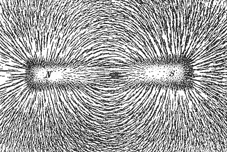
    Field lines can be visualized quite easily in the real world. This is commonly done with iron filings dropped on a surface near something magnetic. Each filing behaves like a tiny magnet with a north and south pole. The filings naturally separate from each other because similar poles repel each other. The result is a pattern that resembles field lines. While the general pattern will always be the same, the exact position and density of lines of filings depends on how the filings happened to fall, their size and magnetic properties.

    • Figure 3: Magnetic field lines around a bar magnet visualized using iron filings.
      Figure 3: Magnetic field lines around a bar magnet visualized using iron filings.

How do we measure magnetic fields?

Because a magnetic field is a vector quantity, there are two aspects we need to measure to describe it; the strength and direction.
The direction is easy to measure. We can use a magnetic compass which lines up with the field. Magnetic compasses have been used for navigation (using the Earth's magnetic field) since the 11ᵗʰ century.
Interestingly, measuring the strength is considerably more difficult. Practical magnetometers only came available in the 19ᵗʰ century. Most of these magnetometers work by exploiting the force an electron feels as it moves through a magnetic field.
Very accurate measurement of small magnetic fields has only been practical since the discovery in 1988 of giant magnetoresistance in specially layered materials. This discovery in fundamental physics was quickly applied to the magnetic hard-disk technology used for storing data in computers. This lead to a thousand-fold increase in data storage capacity in just a few years immediately following the implementation of the technology (0.1 to 100 G, b, i, t, slash, i, n, c, h, squared between 1991 and 2003 [2]). In 2007 Albert Fert and Peter Grünberg were awarded the Nobel Prize in Physics for this discovery.
In the SI system, the magnetic field is measured in tesla (symbol T, named after Nikola Tesla). The Tesla is defined in terms of how much force is applied to a moving charge due to the field. A small refrigerator magnet produces a field of around 0, point, 001, space, T and the Earth's field is about 5, dot, 10, start superscript, minus, 5, end superscript, space, T. An alternative measurement is also often used, the Gauss (symbol G). There is a simple conversion factor, 1, space, T, equals, 10, start superscript, 4, end superscript, space, G. Gauss is often used because 1 Tesla is a very large field.
In equations the magnitude of the magnetic field is given the symbol B. You may also see a quantity called the magnetic field strength which is given the symbol H. Both B and H have the same units, but H takes into account the effect of magnetic fields being concentrated by magnetic materials. For simple problems taking place in air you won't need to worry about this distinction.
Available at https://www.khanacademy.org. Acceso el 10 de octubre, 2020

ACTIVIDADES
CUESTIONARIO
1. ¿Con qué estamos familiarizados según este artículo?
2. ¿De qué depende la atracción de los imanes?
3. ¿Qué describe la región alrededor de un imán?
4. ¿Cómo se describe el campo magnético matemáticamente?
5. ¿Cómo se traza este campo?
6. ¿A dónde apunta cada vector?
7. ¿Qué ilustra la técnica de disposición de los vectores?
8. ¿Qué se considera cuando se mide una cantidad vectorial?
9 ¿Cómo se mide la velocidad?
10. ¿Qué se descubrió en 1988?
11. ¿En dónde se aplica este descubrimiento? 

COMPLETE LAS SIGUIENTES ORACIONES
1. An alternative way to represent the information ...
2. Magnetic field lines naturally ...
3. Sometimes arrowheads ...
4. The field is assumed to follow the lines ...
5. While the general pattern ...

LEA DESDE "How do we measure magnetic fields?" EN ESPAÑOL.


martes, 6 de octubre de 2020

VIDEOS- MECHANICAL SIMULATOR -- CAR MECHANICAL SIMULATOR


JUST ENJOY THESE VIDEOS !!!!!!!!!!
 
Available at https://store.steampowered.com/app/1044980/Mech_Mechanic_Simulator/ and https://store.steampowered.com/app/645630/Car_Mechanic_Simulator_2018/ Acceso el 1 de octubre, 2020.


Mechanical Energy


Mechanical energy transferred to the transducer, such as a Cymbal and a flexible transducer, will be converted into electrical energy through the piezoelectric effect.

From: Metal Oxides in Energy Technologies, 2018 


Concept of energy

Nikolay Belyakov, in Sustainable Power Generation, 2019

1.3.3 Mechanical energy

Mechanical energy can be found in nature in multiple forms, for instance, one can mention:

Pressurized hot gases or other fluids which have enough potential energy that can be turned into kinetic energy of the flow;

Flowing water of the streams and rivers that have enough energy stored in the running water;

Wind, or flowing air, which has the same logic as flowing water;

Waves, tides, ocean streams, etc.

In order to capture this type of energy, special rotating devices called turbines are used. These turbines capture the mechanical energy of the flow and convert it to another type of mechanical energy in the form of rotation. Evidently, due to friction during rotation, some energy is dissipated in the form of heat. Moreover, turbines usually do not capture all mechanical energy of the flow which also negatively contributes to the overall process efficiency.

Next, rotation of the turbine can then be used in multiple ways


Conversion of mechanical energy of the fluid flow (e.g. water or air) is usually done through the mechanical energy of the rotating shaft, which can be further employed for doing work or converted into electrical energy.

Run other machinery, for example, pumps, and do some work;

Run a machine called electrical generator which converts mechanical energy of the rotation to the electrical energy. The physics of the process involves rotating magnetic field that induces current, which is then transferred to the consumer.

It is important to mention that energy of the rotating equipment (wheel or shaft) is an important step within both conventional and emerging energy conversion chains. In many cases this is the only way to transform mechanical energy into electricity through coupling the shaft of the turbine to the electrical generator.

Basic Probability

Chapter 1Basic Probability. 

This chapter is an introduction to the basic concepts of probability theory. 

Chance Events 

Randomness is all around us. Probability theory is the mathematical framework that allows us to analyze chance events in a logically sound manner. The probability of an event is a number indicating how likely that event will occur. This number is always between 0 and 1, where 0 indicates impossibility and 1 indicates certainty. 

A classic example of a probabilistic experiment is a fair coin toss, in which the two possible outcomes are heads or tails. In this case, the probability of flipping a head or a tail is 1/2. In an actual series of coin tosses, we may get more or less than exactly 50% heads. But as the number of flips increases, the long-run frequency of heads is bound to get closer and closer to 50%. 

Flip the Coin 

Flip 100 times 

For an unfair or weighted coin, the two outcomes are not equally likely. You can change the weight or distribution of the coin by dragging the true probability bars (on the right in blue) up or down. If we assign numbers to the outcomes — say, 1 for heads, 0 for tails — then we have created the mathematical object known as a random variable

Expectation

The expectation of a random variable is a number that attempts to capture the center of that random variable's distribution. It can be interpreted as the long-run average of many independent samples from the given distribution. More precisely, it is defined as the probability-weighted sum of all possible values in the random variable's support, 

E[X]=xXxP(x

Consider the probabilistic experiment of rolling a fair die and watch as the running sample mean converges to the expectation of 3.5. 

Roll the Die 

Roll 100 times 

Change the distribution of the different faces of the die (thus making the die biased or "unfair") by adjusting the blue bars below and observe how this changes the expectation. 

Variance 

Whereas expectation provides a measure of centrality, the variance of a random variable quantifies the spread of that random variable's distribution. The variance is the average value of the squared difference between the random variable and its expectation, 

Var(X)=E[(XE[X])2]

Draw cards randomly from a deck of ten cards. As you continue drawing cards, observe that the running average of squared differences (in green) begins to resemble the true variance (in blue).


Available at https://seeing-theory.brown.edu/basic-probability/index.html. Acceso el 1 de octubre, 2020.

martes, 8 de octubre de 2019

READING: AutoCAD


The Importance of AutoCAD to a Mechanical Engineer
by Jeffrey Joyner
Mechanical engineering is a broad field that encompasses industry, business, medicine and even law. Planning and designing mechanical objects is the primary focus of mechanical engineers, whether they are producing engine and motor components or complete devices like refrigerators and robots. Design programs like AutoCAD help mechanical engineers do their jobs by helping them create preliminary designs and spot flaws before production, saving time and resources.
What is AutoCAD?
 CAD stands for "Computer Aided Design." AutoCAD is a line of two-dimensional and three-dimensional design software produced by the Autodesk company. It includes a powerful suite of features to improve workflow and create true-to-life maps, diagrams, structures and schematics. CAD software is equal part design and analysis. The design is needed to produce models and prepare component production, and the analysis helps calculate stress levels, the influence of forces and the influences of finite elements in a design. According to a General Electric survey, 60 percent of manufactured parts errors were related to incomplete, ambiguous or impossible drafts -- problems easily corrected with the support of software like AutoCAD.

Design Production and Troubleshooting
At the earliest stages of a design project, mechanical engineers can use AutoCAD to start sketching ideas and analyzing them to determine the best solution for a given problem. The software makes the process quick and easy; it eliminates the need to draw new blueprints for each version of an idea and simplifies redesigns. The software additionally helps interpret these designs, locating flaws, errors and inconsistencies the mechanical engineer might miss. Alternatively, the mechanical engineer can use AutoCAD to determine the source of a malfunction in an existing product by putting in the specifications and allowing the software to find the problem, allowing the engineer to be more efficient by going straight to the problem and finding a fix.

Simulations and Scenarios
One of the most useful functions of AutoCAD is its ability to provide a graphic simulation of how a constructed machine will function. Once a design prototype is complete in the software, AutoCAD can generate a simulated version of the prototype and show it in action. This is a function impossible for the mechanical engineer to otherwise reproduce without investing the time and resources in developing a real-life prototype. With the help of this simulation, mechanical engineers can determine if the machine will work as intended and make any necessary tweaks or fixes before it goes into production.

Quality Assurance and Control
Thanks to the analysis components of AutoCAD, mechanical engineers can simulate a variety of environments and stresses upon a prototype. This allows them to determine the functionality of a part or machine in extreme environments or under high-stress conditions difficult to test outside simulation. These simulations also provide a demonstration of a prototype's expected performance over time, allowing accurate estimates to be made on a machine's functional life span before requiring maintenance or replacement. AutoCAD allows mechanical engineers to produce useful specifications and give clients exactly what they need in an efficient time frame.

Available at: https://work.chron.com/importance-autocad-mechanical-engineer-26569.html [Acceso el 6 de octubre, 2019]


                                                                    Image from Google images.

READING: The Pros and Cons of Diesel Engines


The Pros and Cons of Diesel Engines

If you’re considering buying a new automobile, compare the pros and cons of diesel-powered vehicles. Consider these facts to help you decide between an engine powered by diesel fuel and a gasoline-powered one:
  • PRO: Diesels get great mileage. They typically deliver 25 to 30 percent better fuel economy than similarly performing gasoline engines. Diesels also can deliver as much or more fuel economy than traditional gasoline-electric hybrids, depending on the models involved and whatever rapidly developing automotive technology achieves.
  • CON: Although diesel fuel used to be cheaper than gasoline, it now often costs the same amount or more. Diesel fuel is also used for commercial trucks, home and industrial generators, and heating oil, so as demand for diesel passenger vehicles grows, the price of diesel fuel is likely to continue to rise because of competition from those other users.
Even if the price goes up, diesel fuel would have to be 25 to 30 percent more expensive than gas to erase the cost advantage of a diesel engine’s greater fuel efficiency.
  • PRO: Diesel fuel is one of the most efficient and energy dense fuels available today. Because it contains more usable energy than gasoline, it delivers better fuel economy.
  • CON: Although diesel fuel is considered more efficient because it converts heat into energy rather than sending the heat out the tailpipe as gas-powered vehicles do, it doesn’t result in flashy high-speed performance. In some ways, a gasoline-powered engine is like a racehorse — high-strung, fiery, and fast — whereas a diesel engine is more like a workhorse — slower, stronger, and more enduring.
  • PRO: Diesels have no spark plugs or distributors. Therefore, they never need ignition tune-ups.
  • CON: Diesels still need regular maintenance to keep them running. You have to change the oil and the air, oil, and fuel filters. Cleaner diesel fuels no longer require you to bleed excess water out of the system, but many vehicles still have water separators that need to be emptied manually.
  • PRO: Diesel engines are built more ruggedly to withstand the rigors of higher compression. Consequently, they usually go much longer than gas-powered vehicles before they require major repairs. Mercedes-Benz holds the longevity record with several vehicles clocking more than 900,000 miles on their original engines! You may not want to hang onto the same vehicle for 900,000 miles, but longevity and dependability like that can sure help with trade-in and resale values.
  • CON: If you neglect the maintenance and the fuel injection system breaks down, you may have to pay a diesel mechanic more money to get things unsnaggled than you would to repair a gasoline system because diesel engines are more technologically advanced.
  • PRO: Because of the way it burns fuel, a diesel engine provides far more torque to the driveshaft than does a gasoline engine. As a result, most modern diesel passenger cars are much faster from a standing start than their gas-powered counterparts. What’s more, diesel-powered trucks, SUVs, and cars also can out-tow gas-powered vehicles while still delivering that improved fuel economy.


martes, 9 de septiembre de 2014

IMPERATIVE - Differential Carrier Installation

Differential Installation Instructions
Please read completely before beginning.
Disassembly


Make sure that you have all the parts and tools you will need. The extent of disassembly depends on the job being done and the inspection findings. Lift the vehicle using an appropriate lift or a jack and safe jack stands. Always make certain that the vehicle is safely supported before working underneath. 
Unbolt the driveshaft from the yoke. 
Remove the differential cover or unbolt the third member. Let the oil drain into a suitable container. 
Please recycle your waste oil. 
Remove c-clip axles by removing the differential cross pin bolt and cross pin shaft, pushing the axles in and pulling the c-clips. Full float axles are unbolted at the hubs. 

Punch both carrier caps with identification marks so that you will be able to re-install them on the same side and in the same direction. Most carriers can be pried out of the housing with a pry bar. Further disassembly depends on the job being done. If you’re changing the ring and pinion or the pinion bearings, remove the pinion nut with an air gun while holding the yoke, or use a long breaker bar and brace the yoke (bolt it to a long board) so that it can’t move. 
Knock the pinion gear out to the rear with a brass punch, taking care not to damage the threads. 
Keep track of the location and thickness of all of the original shims. Pinion bearings must be pressed off. Carrier bearings can be pulled using a bearing puller. Internal parts (inside the carrier) can be removed as necessary.

                                      Source: http://www.differentials.com/technical-help/installation-instructions